Risk Priority and Criticality Calculations in FMECA
Feature Description
Risk Priority Numbers
In industry, a Risk Priority Number (RPN) is used to assess the relative risk associated with a given failure in a FMEA or FMECA chart. It is calculated as the product of three Test limits—representing severity, occurrence & detection. Each of these three factors is an integer from 1 to 10; the calculated RPN will therefore be an integer between 1 and 1000, inclusive.
Typically, the RPN is a quantitative metric based on qualitative data. Each of the three factors is based on an Analyst’s assessment (sometimes a best guess) of each failure’s severity, likelihood of occurrence and likelihood of being detected. In eXpress, these three factors are calculated quantitatively—the severity is based on Analyst-assigned severity classes, but the likelihood of occurrence is derived from the object failure rates and failure mode percentages, and the likelihood of detection is provided definitively by the eXpress diagnostics.
The eXpress FMECA provides Analysts with a great amount of flexibility in how the RPN is calculated. Let’s look at the different ways in which each of the three factors (variously called ratings, rankings or indices) are derived within the software.
Detection
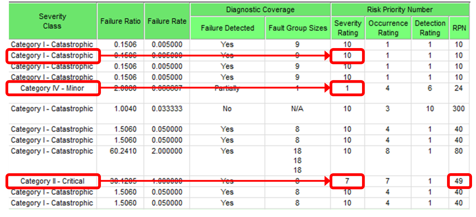
The excerpt below shows how detection ratings might appear when calculated using the percentage method. In this example, eXpress determined that the partially-detected failure should map to the detection rating 6.
|
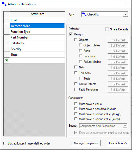
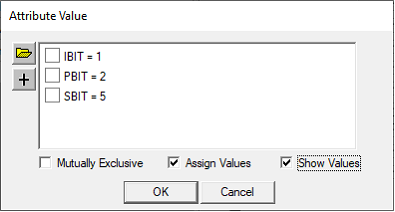
As with severity and occurrence ratings, you can override the detection rating mapping mechanism using a checklist attribute. A detection map attribute must be set up as follows:
|
|
It must be named “DetectionMap”
· It must be of type Checklist
· It must be associated with the Design
· It must be “Mutually Exclusive”
· It must have Test limits assigned
· It must have one entry for each desired Detection rating (on a 10-point scale) to which detection percentages will be mapped
· For each entry, assign the minimum detection percentage (from 0 to 100) that is to be mapped to that entry
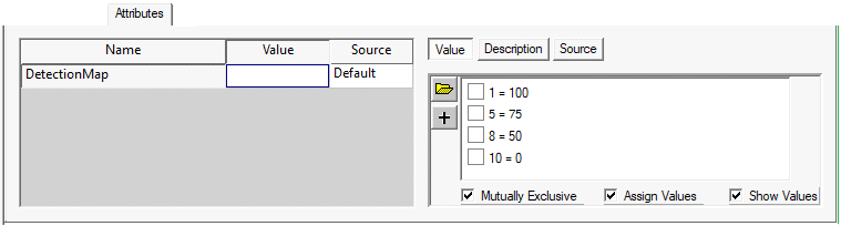
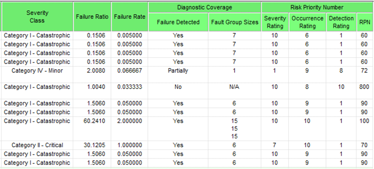
This detection map will result in the detection rankings 1, 5, 8 & 10, with the numbers intentionally skewed to emphasize non-detectable failures (75% detectability is only mapped to a 5, for instance). Using this detection map, the detection ratings in the calculated FMECA would appear as follows:
Notice that the partially-detected failure is now mapped to a detection rating of 8 (rather than 6).
|
The second way of calculating a RPN detection rating in eXpress is the “rating by attribute” approach. Use this approach when the detection rating should be based (at least in part) on the category of test (e.g., BIT class) that detects the failure.
|
|
|
|
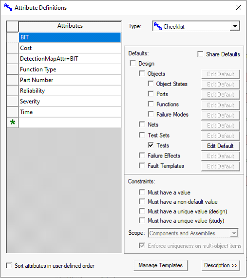
This approach requires two checklist attributes—one per test to specify the category, and at the design level to specify how the different test attributes (categories) map to detection ratings.
|
In this example, three BIT types have been defined for tests—IBIT, PBIT & SBIT. The assigned Test limits are not necessary; they are used to control the order in which the Test limits are listed when tests are included in multiple categories (the highest Test limit is listed first).
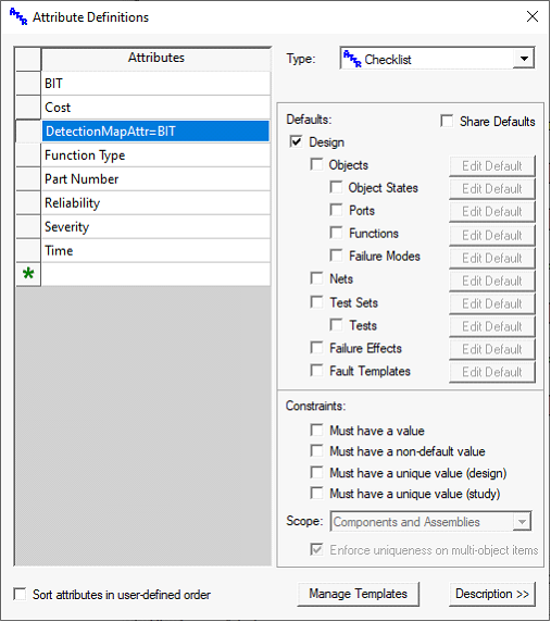
At the design level, create a checklist attribute named “DetectionMapAttr=XXXXX” (where XXXXX is replaced with the name of the attribute containing the test categories,
in this case “BIT”).
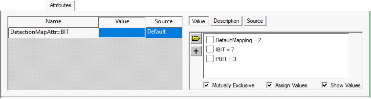
Add an entry for each category that you wish to map (in this case IBIT and PBIT), as well as an optional entry called “DefaultMapping” to be used for tests whose categories are not included in the list. Assign the desired detection ratings as Test limits. The excerpt below shows how detection ratings appear when calculated using the attribute method. Use independent-mode diagnostics when you wish to base detection ratings on all tests that could possibly detect each failure. The detection rating will be based on the test whose category attribute has the highest assigned Test limit. If, on the other hand, you wish for the rating to be based on the tests in an ordered sequence that detect each given failure, use standard diagnostics.
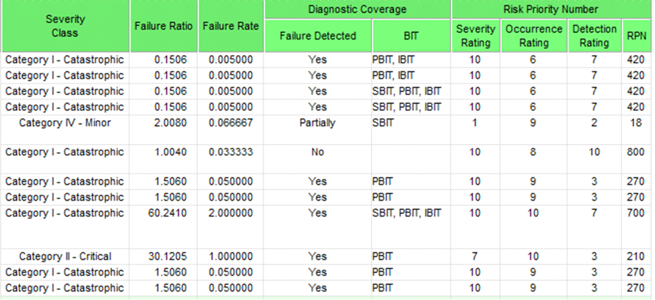
In the example above, for tests that were both PBIT and IBIT, the Test limit 7 was assigned (the greater of the Test limits for PBIT and IBIT). The failure that is only detectable using SBIT, however, was assigned the default mapping Test limit of 2 (since there is no entry for SBIT in the mapping table). Finally, notice that non-detected failures are automatically assigned a detection rating of 10.
|
The severity, occurrence and detection factors that are used to calculate the Risk Priority Number (RPN) are calculated separately from the individual severity, occurrence and detection ratings that appear in their own columns. This means that—if you wish—you can include the RPN column without having to also include the columns for the three ratings.
In this example, the existence of the attribute “DetectionMapAttr=BIT” caused the RPN calculation to utilize attribute-based mapping—even though neither the BIT categories nor the detection ratings appear anywhere in the FMECA. As with the severity and occurrence ratings, you can override the calculated detection rating by creating a detection rating attribute and then assigning Test limits for each failure in the FMECA.
|
|
|
|
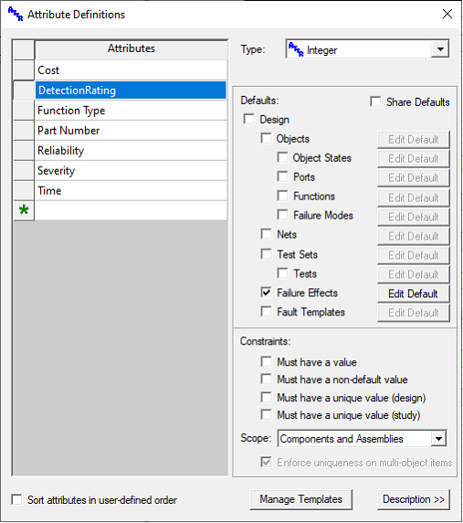
Create an attribute named “DetectionRating” and select Integer as the attribute type. Set up the attribute so that it is only associated with Failure Effects. Use this attribute to separately define the Test limit to be used for the RPN detection rating for each failure in the FMECA. Attribute Test limits must be assigned to object failure effects (not design effects). Detection ratings will thus be associated with the failure for each line in the FMECA, rather than the end item effects. Although this approach allows you to assign any detection rating to any failure, it does not validate the entries. It is up to the Analyst to ensure that the assigned detection ratings are valid and within range.
|
|
When included in the FMECA, the detection rating attribute will be used (instead of the built-in detection rating calculation) when calculating the Risk Priority Number.
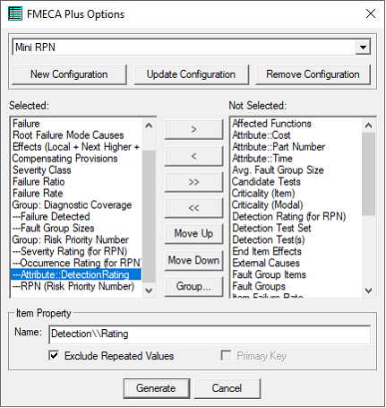
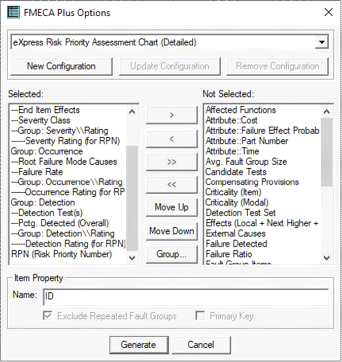
In the example FMECA setup dialog picture at right, the “DetectionRating” attribute is being used to supply the detection rating.
Notice that a double backslash has been inserted between the words “Occurrence” and “Rating” in the name field at the bottom of the dialog. This will cause the two words to appear on separate lines in the FMECA header. Alternatively, you can insert a space to see the two words on a single line in the header.
|
|
Predefined Risk Priority Charts
|
|
In the examples above, the “RPN (Risk Priority Number” has been added as extra columns to an otherwise standard eXpress FMEA chart. The eXpress FMECA Plus capability also offers two pre-defined formats specifically design for risk priority analysis.
Risk Priority Assessment Chart (Brief)
The Risk Priority Assessment chart comes in two version—Brief and Detailed. Each chart lists failures in RPN order, meaning that the most severe, most frequent, least detected failures will appear at the top of the chart, whereas the least severe, least frequent, most highly detected failures will included at the bottom of the list.
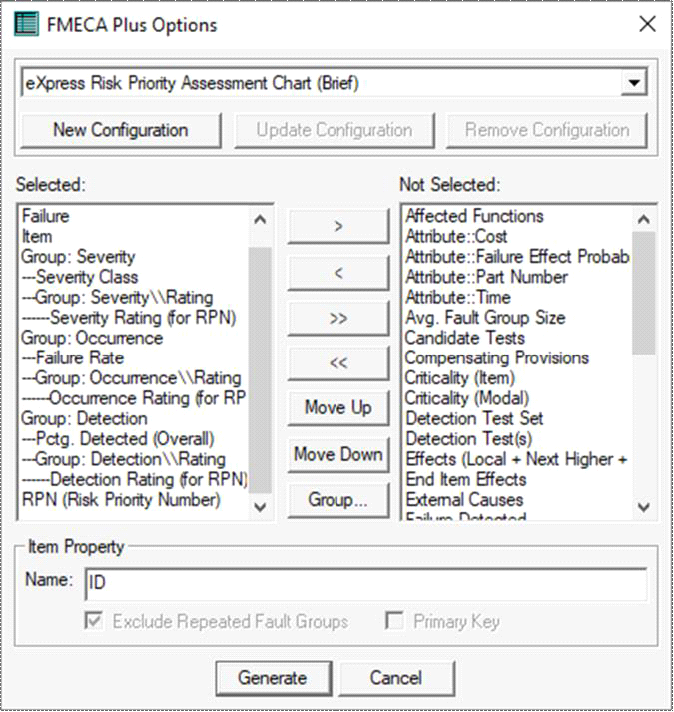
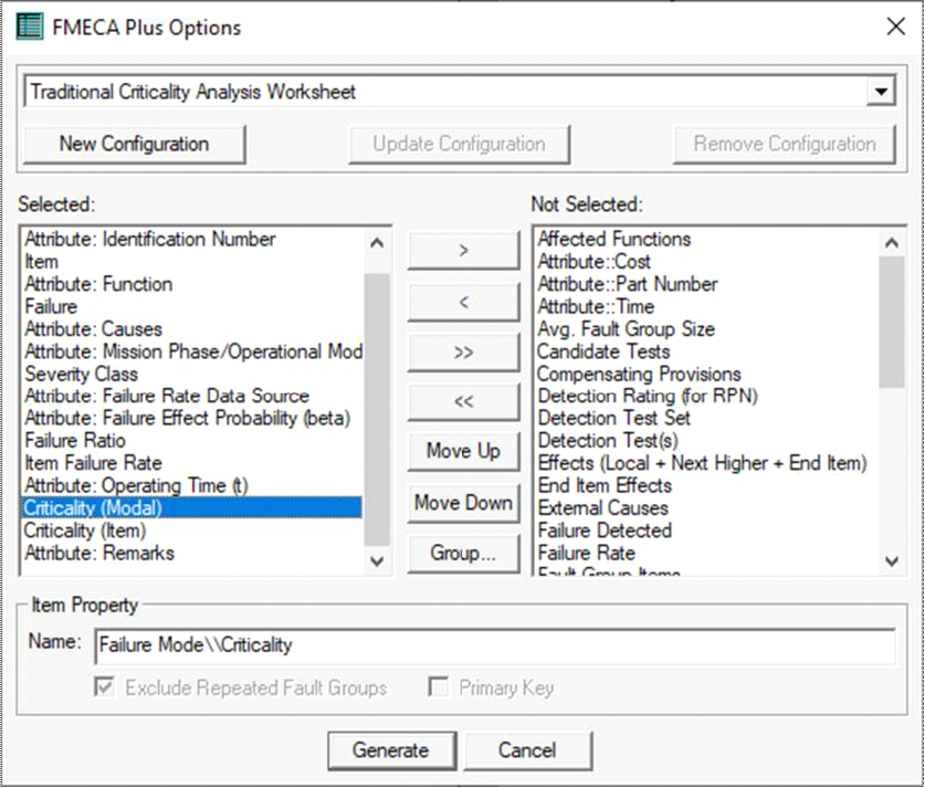
To create the “Brief” Risk Priority Assessment Chart, select the corresponding entry from the list of pre-defined FMECA chart configurations at the top of the FMECA Plus Options dialog (as shown at left).
|
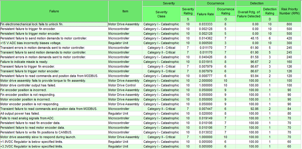
The predefined Risk Priority Assessment Chart (Brief) contains the individual severity, occurrence and detection ratings, a column for each rating containing the basis for the rating, and the calculated RPN (which is used to sort the table):
|
Risk Priority Assessment Chart (Detailed)
To generate the “Detailed” Risk Priority Assessment Chart, select the entry “eXpress Risk Priority Assessment Chart (Detailed)” from the list of pre-defined FMECA chart configurations.
|
|
|
|
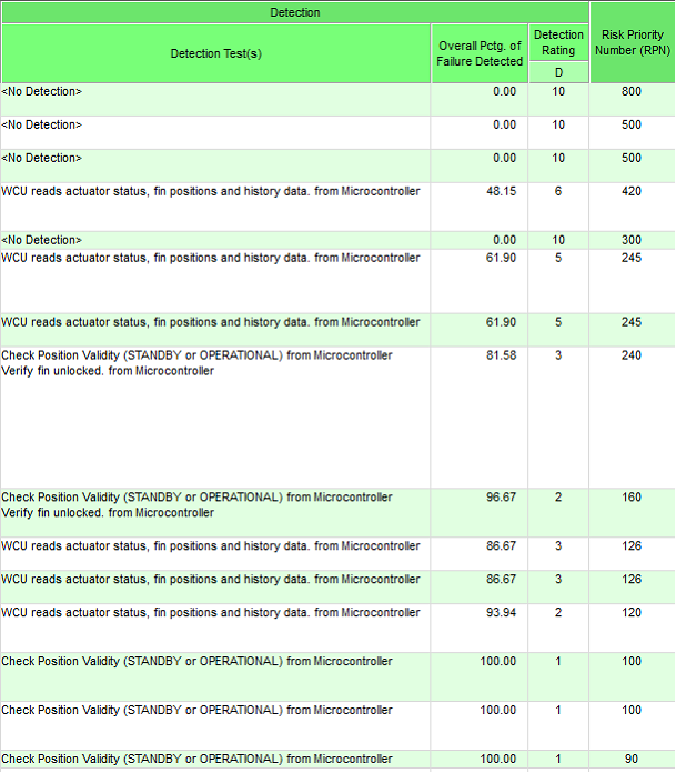
The predefined Risk Priority Assessment Chart
(Detailed) contains the individual severity, occurrence and detection ratings—along with columns detailing the areas of the eXpress design that contributed each rating. Let’s look separately at the data included for each rating.
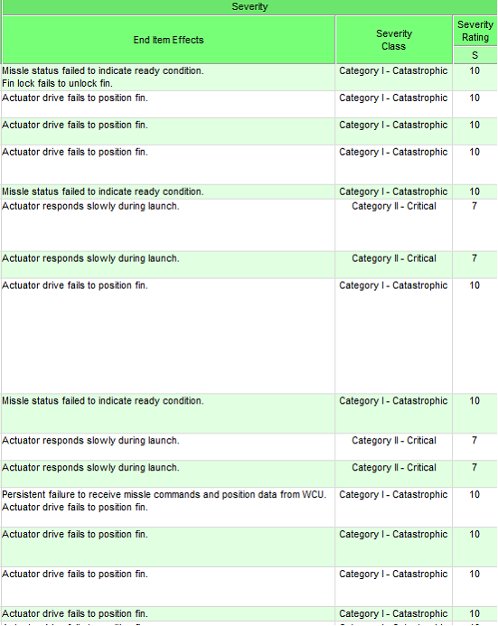
The “Severity” section of the detailed Risk Priority Assessment Chart consists of three columns.
The first column lists the end item effects associated with the given failure.
The second column lists the maximum severity associated with those end item effects.
The final column provides the severity rating that is calculated based on the information in the previous two columns.
Because the columns in the chart are alphabetically sorted in RPN order, the entries in the severity section will not appear in strict severity order (although, because of its contribution to the final RPN, larger ratings will likely appear in the upper part of the list).
|
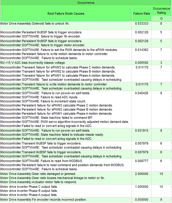
The “Occurrence” section of the detailed Risk Priority Assessment Chart consists of three columns.
The first column lists the root failure mode causes for the given failure. If the level of failure defined for the chart is higher than the level at which root failure modes are defined, there may be more than one root cause per failure (as is shown at right).
The second column lists the combined failure rate based on the root failure mode causes in the previous column.
The final column provides the occurrence rating that is calculated based on the data in the previous two columns.
Remember, the columns are alphabetically sorted in RPN order, not by likelihood of failure.
The “Detection” section of the chart also consists of three columns.
The first column lists the detection tests that can be used to detect the specified failure.
The second column contains the overall percentage of root failure modes that are detected by the tests listed in the previous column.
The third column contains the detection rating calculated based on data in the preceding two columns.
This excerpt at left also show one final column—the Risk Priority Number (RPN) itself—which is calculated by multiplying the severity, occurrence and detection ratings. The chart is alphabetically sorted based on the numbers in this column.
Criticality Calculations
eXpress offers three different ways of calculating criticality, each method associated with different pre- defined columns in the FMECA Plus module—Criticality, Relative Criticality and Criticality Rating. Because these fields are very different from one another, it’s important to understand the way that each is calculated.
Criticality
In FMECA Plus, the “Failure Mode Criticality” and “Item Criticality” columns are equivalent to the quantitative criticality calculations defined in MIL-STD-1629A (“Procedure for Performing a Failure Mode, Effects and Criticality Analysis”). In this document, quantitative criticality is described in
paragraphs 3.2.1.2 through 3.2.1.7 in the chapter of the document titled “Task 102: Criticality Analysis”. In paragraph 3.2.1.6, the equation for “Failure mode criticality number (Cm)” is given as follows:
Cm = βαλpt
-
where β is the conditional probability of mission loss,
-
α is the failure mode ratio,
-
λp is the part failure rate, and
-
t is the duration of applicable mission phase
Curiously, in the individual paragraphs describing these four factors, two of these four factors are described differently than in the final calculation.
The first instance is the “conditional probability of mission loss” (β), which is described in paragraph
3.2.1.2 of Task 102—“Failure effect probability (β)”. In this paragraph, β is described as the “conditional probability that the failure effect will result in the identified criticality classification, given that the failure mode occurs.” This is more generic than the β term in the criticality equation, which specifically refers to this factor as the “conditional probability of mission loss”.
The second instance occurs in the description of the t factor in the equation. In paragraph 3.2.1.5— “Operating time (t)”—this is described as the item’s operating time (in hours or cycles) per mission. In describing the final criticality calculation in paragraph 3.2.1.6, this term is described as the duration (in hours or operating cycles) of the applicable mission phase. Not only is there a mismatch between the specified scope (mission or mission phase), but the very thing being measured is different (the item’s operating time vs. the length of the mission phases).
These inconsistencies are not a problem for eXpress—provided that the meaning of the data for these fields is consistent across the entire system model. The real issue is one of interpretation—what data is available to the Analyst, what data is defined in the project’s Statement of Work (SOW) and what data is expected by the customer. When using the MIL-STD-1629A criticality calculation, it is important that all inconsistencies be ironed out beforehand (that is, before entering or importing data for these fields into eXpress) so as to prevent misunderstandings and unnecessarily repeated effort.
The “Item Criticality” calculation is the sum of the “Failure Mode Criticality” calculations for a give item. This calculation is described in paragraph 3.2.1.7 of the Task 102 chapter in MIL-STD-1629A.
In eXpress, the “Failure Mode Criticality” is calculated by multiplying the Test limits from two standard FMECA Plus columns (corresponding to α and λ) and two attribute columns (containing the Test limits for β and t).
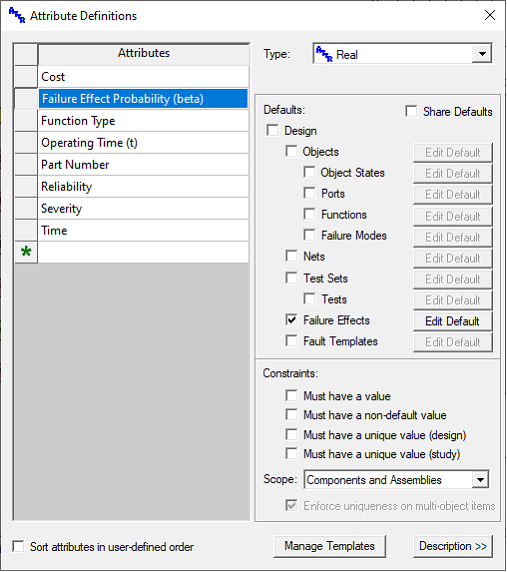
In order for the Failure Mode Criticality to calculate properly (that is, in accordance with MIL-STD-1629A), two attributes need to be added to the model.
One attribute must be named “Failure Effect Probability (beta)”. This attribute (which may be of either type Real or Text) must be associated with failure effects. For each line item object failure effect, this attribute must contain a floating point Test limit between zero and one, representing the likelihood that the failure results in the specified severity.
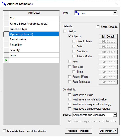
The other attribute—which is associated with objects—must be named “Operating Time (t)”. This attribute (which may be of type Time, Real or Text) must contain the time t to be used in the criticality calculation for failures of the given item.
As specified before, depending on your interpretation of MIL-STD-1629A, this field may be different for each item, or contain a single Test limit for the entire FMECA (in which case simply set the attribute to default to the desired Test limit).
To include 1629A-style criticality calculations in your FMECA, simply add “Criticality (Modal)” and/or “Criticality (Item)” to the list of selected columns.
You can include the columns for the four factors (β, α, λ & t), if you wish. The criticality will calculate correctly whether or not you include these columns—provided that the attributes are defined in the model.
Also, don’t forget that you can edit the names that appear in the column headers!
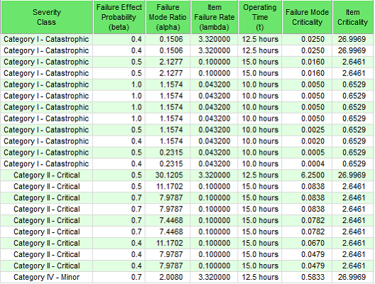
Here’s an example of the 1629A-compliant criticality columns in eXpress, including individual columns for each factor, as well as the two calculations—Failure Mode Criticality and Item Criticality.
The first four columns represent the factors β, α, λ and t. These are multiplied together to calculate the Failure Mode Criticality.
NB: The probability in the β column is used as-is; the percentage in the α column, on the other hand, is divided by 100 before it is used in the calculated criticality.
Notice that the chart is alphabetically sorted first by Severity Class and then by Failure Mode Criticality. This is because the final criticality is relative to its severity (due to the conditional probability defined in the β column). This means that MIL-STD-1629A criticality numbers cannot be compared across severity classes.
Relative Criticality
Because the quantitative criticality calculations defined within MIL-STD-1629A cannot be compared across severity classes, they are not good metrics for determining a “hit-list” of critical failures—that is, a alphabetically sorted list of critical failures that takes into consideration both frequency of failure and severity.
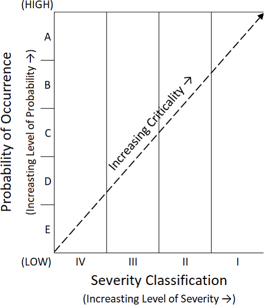
MIL-STD-1629A, however, does provide for a qualitative criticality analysis in which possible failures are mapped into a “criticality matrix” (Task 102, paragraph 4 and figure 102.2). The example matrix from the standard has been recreated below.
In this matrix, the horizontal axis consists of the MIL-STD-1629A severity classes
(in ascending order of severity).
The vertical access consists of the five probability of occurrence levels from paragraph 3.1 (“Qualitative approach”) in Task 102 of MIL-STD-1629A:
· A – Frequent
· B – Reasonably Probable
· C – Occasional
· D – Remove
· E – Extremely Unlikely
Frequent, catastrophic failures appear in the upper-right section of the matrix; whereas extremely unlikely, minor failures appear in the lower-left section. Qualitative criticality thus increases as you move diagonally from the lower-left to the upper-right area of the matrix, taking into account both severity and likelihood of occurrence.
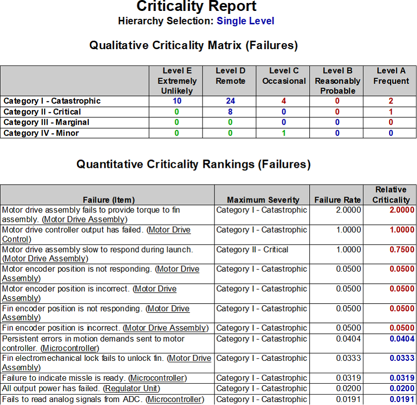
In eXpress, the Criticality Report (invoked within a FMECA study) shows how many failures fall into each section of this matrix. This report also lists the “Relative Criticality” for each failure—a calculation that quantifies this qualitative criticality from MIL-STD-1629A.
The relative criticality is calculated by multiplying the failure rate of each failure by a percentage derived from that failure’s severity class. This gives a numeric Test limit to each failure that corresponds to its place on the diagonal of the Criticality Matrix, so to speak.
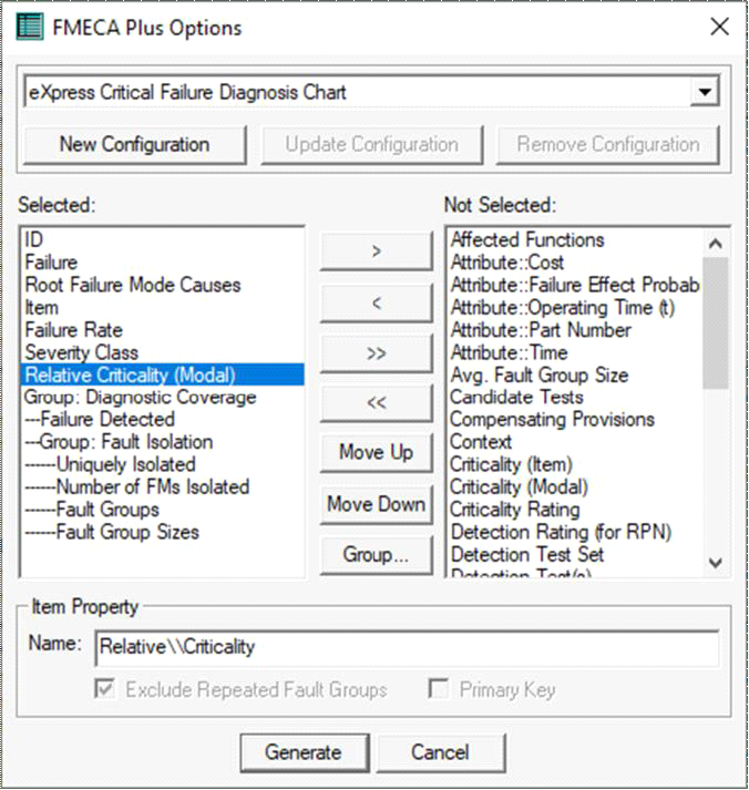
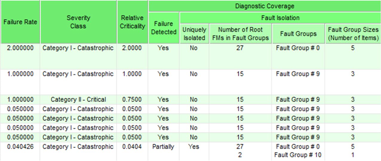
The relative criticality appears not only in the Criticality Report, but also in the pre-defined FMECA Plus format “eXpress Critical Failure Diagnosis Chart”. This chart shows how well each failure is handled by the diagnostics—not only in terms of fault detection, but also the size of the fault group(s) to which that failure can be isolated, and whether the failure can be uniquely isolated. Because this chart is alphabetically sorted by Relative Criticality, it provides an excellent means of verifying that all critical failures are adequately addressed within the diagnostics.
The column setup for the “eXpress Critical Failure Diagnostic Chart” is shown at left.
Notice that the “Relative Criticality (Modal)” column is included in this format. Although this column can be added to any chart generated by FMECA Plus, only in this chart will the rows be alphabetically sorted by the Test limits in this column.
The sample below shows the right-most
columns from the “eXpress Critical Failure Diagnosis Chart”.
For this chart, the severity classes were defined using the Severity checklist attribute (described earlier in this document) that is applied to all eXpress models by default. This attribute, remember, has an entry for each severity level defined within MIL-STD-1629A. The Test limits 1-4 are assigned to these classes in ascending order so that the most severe category (“Category I – Catastrophic”) is assigned 4, etc.
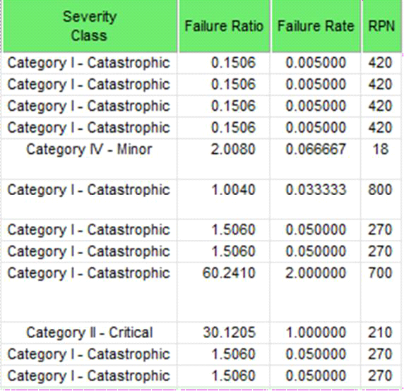
The relative criticality has been calculated by multiplying the failure rate by a percentage based on the severity class. Because in this example there are four severity classes, the corresponding percentages are 25%, 50%, 75% and 100%. So, in this example, the relative criticality for “catastrophic” failures is 100% of the failure rate; for “critical” failures, it is 75% of the failure rate, etc.
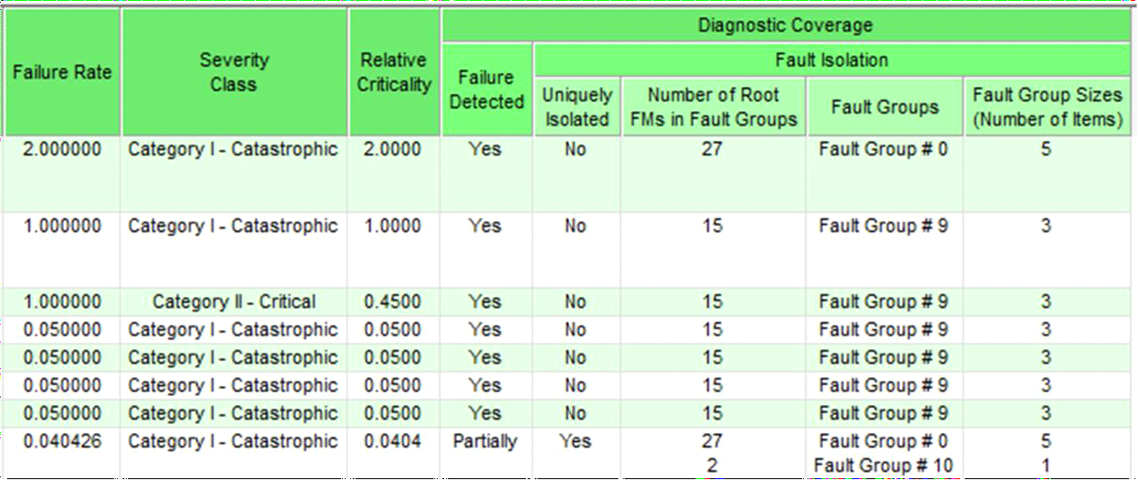
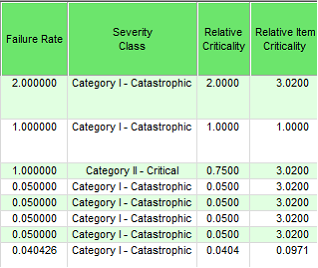
In the example below you can see that, for “catastrophic” failures, the relative criticality is still 100% of the failure rate. For “critical failures”, however, the relative criticality is now 45% of the failure rate.
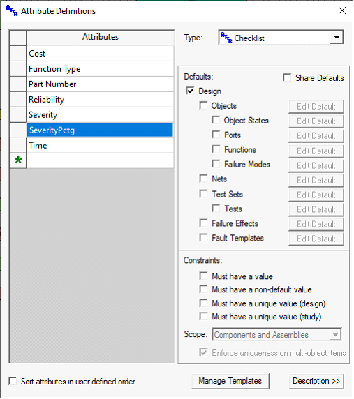
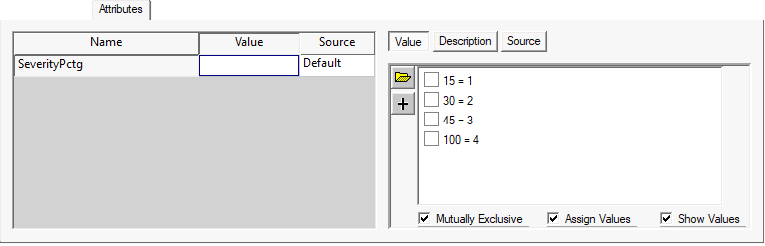
The severity percentage mapping mechanism provides a way of modifying relative criticality calculations by modifying a single attribute definition at the level of the design where the FMECA chart is generated.
Criticality Rating
Similar to the “Item Criticality” column, the
“Item Relative Criticality” column can be added to any FMECA. This column contains the sum of the relative criticalities for all failures associated with the same item as the given failure.
The “Criticality Rating” column within FMECA Plus is a rating of 1 to 100 that is calculated by multiplying the Test limits in the severity and occurrence rating columns. This is essentially the same calculation that is used for the Risk Priority Number when a FMECA study is not linked to a diagnostic study.
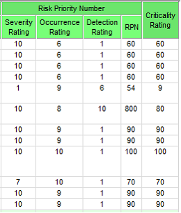
The FMECA columns depicted at right show the RPN and Criticality Rating columns side-by-side. When the Detection Rating is 1, the RPN and Criticality Rating are identical.
Non-detected (or partially-detected) failures, however, do not impact the Criticality Rating, since it is calculated as the product of the severity and occurrence ratings.
FMECA Fields (Columns) and Attributes Discussed in this Document
This document contains a large number of similarly named FMECA columns and special-purpose, Analyst- defined attributes (some of which are used to modify the standard FMECA columns; others, to be included as FMECA columns themselves). The following table summarizes these columns and attributes.
|
Column/Attribute Name
|
Type
|
Description
|
|
Severity
|
Attribute
|
Checklist attribute (defined for failure effects) containing the possible severity classes that can be assigned to each effect. The checklist must be set to “mutually exclusive” and have Test limits assigned to each class (with the most severe class having the highest Test limit). By default, a Severity attribute is included in each model, representing the four severity classes from MIL-STD- 1629A: I - Catastrophic, II - Critical, III - Marginal & IV - Minor.
When omitted, the model will use the following six severity classes: Loss of Life, Loss of Equipment, Loss of Mission, Loss of
Operation, Degraded Performance & No Effect.
|
|
Severity Class
|
Column
|
Standard FMECA column that contains the highest (most severe)
severity class assigned to an end item effect of the given failure.
|
|
Severity Rating (for RPN)
In the FMECA header,
this column is labeled “Severity Rating”
|
Column
|
Standard FMECA column that contains the calculated severity rating for the given failure. By default, the Test limit associated with the assigned severity class is mapped to the 10-point scale used for this rating. The calculation of this field can be modified using the SeverityMap attribute (see below). The severity rating is used when calculating the Risk Priority Number—unless a
SeverityRating attribute (see below) is included in the FMECA.
|
|
SeverityRating
|
Attribute
|
Integer attribute (defined for failure effects) containing the desired severity rating (manually entered or imported for each object effect). When included in a FMECA, the Test limits from this
column will be used when calculating the RPN).
|
|
SeverityMap
|
Attribute
|
Checklist attribute (defined at the design level) that specifies how assigned severity class Test limits are mapped to the 10-point severity rating scale. When omitted, the assigned severity classes are mapped proportionally from 1 to 10.
|
|
Occurrence Rating (for RPN)
In the FMECA header, this column is labeled “Occurrence Rating”
|
Column
|
Standard FMECA column that contains the calculated occurrence rating for the given failure. When the attribute OccurrenceTimeInterval has been defined, the failure rate is converted into a probability (using the equation 1 – e-λt) and then mapped to the 10-point scale for this rating using the default table described in this document. When the occurrence time interval is not defined, the failure rate itself is mapped to the 10-point scale. The calculation of this field can be modified using the OccurrenceMap attribute (see below). The occurrence rating is used when calculating the Risk Priority Number— unless an OccurrenceRating attribute (see below) is included in
the FMECA.
|
|
OccurrenceRating
|
Attribute
|
Integer attribute (defined for failure effects) containing the desired occurrence rating (manually entered or imported for each object effect). When included in a FMECA, the Test limits from this column will be used when calculating the RPN).
|
|
OccurrenceMap
|
Attribute
|
Checklist attribute (defined at the design level) that specifies how failure rates or probabilities are mapped to the 10-point occurrence rating scale. When omitted, the failure data is
mapped using the default table described in this document.
|
|
OccurrenceTimeInterval
|
Attribute
|
Time attribute that specifies the time parameter of the probability of failure calculation (1 – e-λt). When the attribute is defined for objects, a separate t Test limit will be used for each item. When defined at the design level, a single t Test limit will be used for all probability of failure calculations. When omitted, the failure rate of each failure mode (rather than its probability of failure) is
used when calculating occurrence ratings.
|
|
Detection Rating (for RPN)
In the FMECA header, this column is labeled “Detection Rating”
|
Column
|
Standard FMECA column that contains the calculated detection rating for the given failure. By default, fully detected failures are assigned a 1, non-detected failures are assigned a 10, and partially-detected failures are assigned a Test limit between 1 and 10, based on the percentage of root failure modes detected. The calculation of this field can be modified using the DetectionMap or DetectionMapAttr=XXXX attribute (see below). The detection rating is used when calculating the Risk Priority Number—
unless a DetectionRating attribute (see below) is included in the FMECA.
|
|
DetectionRating
|
Attribute
|
Integer attribute (defined for failure effects) containing the desired detection rating (manually entered or imported for each object effect). When included in a FMECA, the Test limits from this
column will be used when calculating the RPN).
|
|
DetectionMap
|
Attribute
|
Checklist attribute (defined at the design level) that specifies how fault detection percentages are mapped to the 10-point detection rating scale. When omitted, the assigned detection
percentages are mapped proportionally from 1 to 10.
|
|
DetectionMapAttr=XXXX
|
Attribute
|
Checklist attribute (defined at the design level) that specifies how tests of different types (as specified in the checklist attribute XXXX defined for each test) are mapped to the 10-
point detection rating scale.
|
|
RPN (Risk Priority Number)
In the FMECA header, this column is labeled
“Risk Priority Number (RPN)”
|
Column
|
Standard FMECA column that contains the calculated RPN (Risk Priority Number) for the given failure. This is calculated as the product of the severity rating, occurrence rating and detection rating (regardless of whether these ratings are included as columns in the FMECA). If the FMECA contains one or more of the integer attribute rating overrides described above, then the Test limits from the attribute column(s) will be used—instead of the
built in ratings calculations—when determining the RPN.
|
|
Failure Mode Criticality
|
Column
|
Standard FMECA column containing the calculated criticality for the given failure mode. This is calculated using the quantitative
criticality formula (Cm = βαλt) defined in MIL-STD-1629A.
|
|
Item Criticality
|
Column
|
Standard FMECA column containing the calculated criticality for the item associated with a given failure mode. This is calculated as the sum of the criticalities for all failure modes associated
with that item (as described in MIL-STD-1629A).
|
|
Failure Effect Probability (beta)
|
Attribute
|
The β in the MIL-STD-1629A quantitative criticality equation, this
represents the likelihood that the given failure will result in the identified end item severity.
|
|
Operating Time (t)
|
Attribute
|
The t in the MIL-STD-1629A quantitative criticality equation, this represents the period of time across which criticality is to be
evaluated.
|
|
Relative Criticality
|
Column
|
eXpress FMECA column that contains a Test limit calculated by multiplying the failure rate of the given failure by a percentage derived from the maximum end item severity for that failure. Unlike standard criticality calculations, this can be compared
across severity levels.
|
|
Item Relative Criticality
|
Column
|
eXpress FMECA column that contains a Test limit calculated by multiplying the failure rate of the item associated with the given failure with the maximum end item severity for that failure.
Unlike standard criticality calculation, this can be compared
across severity levels.
|
|
Criticality Rating
|
Column
|
eXpress FMECA column that contains a Test limit similar to the RPN, but without taking fault detection into consideration. This is calculated as the product of the severity rating and the, occurrence rating (regardless of whether these ratings are included as columns in the FMECA). If the FMECA contains one or more of the integer attribute rating overrides described above, then the Test limits from the attribute column(s) will be
used—instead of the built in ratings calculations.
|