You have the ability to define intermediate effects—failure effects that represent behavior that occurs at a level between that of the object and design effects.
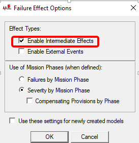
By default, intermediate effects are disabled in each newly created model. If you wish to add intermediate effects to a model, you must first enable intermediate effects using the Failure Effect Options dialog. (Note: This option cannot be disabled for designs that already contain intermediate effects).
If you would like to include intermediate effects in all future models, then select the “Use these settings for newly created models” option on this dialog.
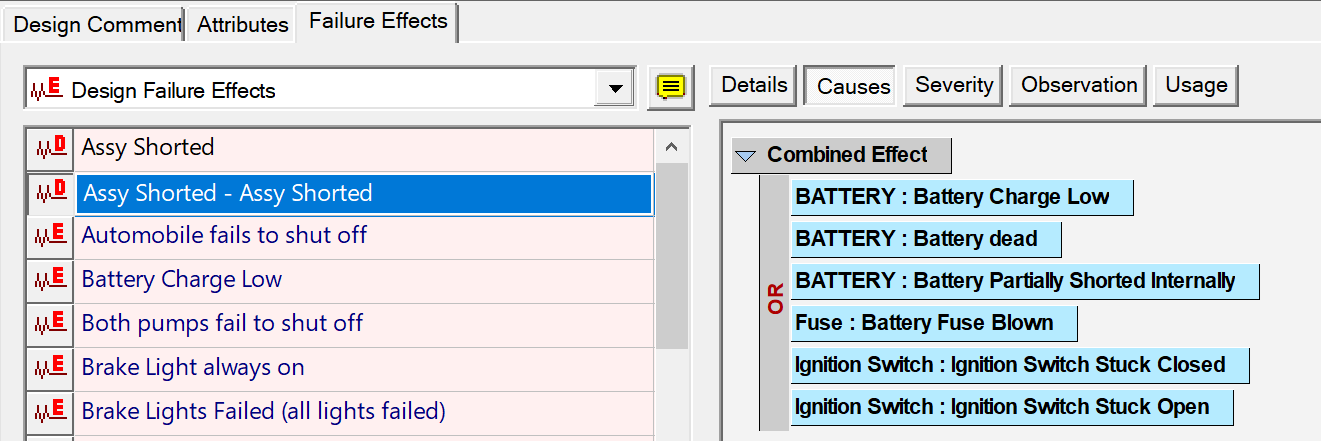
When intermediate effects have been enabled within a design, the header of the effect list on the design Failure Effects panel will become a dropbox, allowing you to choose whether you wish to display (and edit) design effects or intermediate effects:
Design Effect Window:
Design effects may now include any combination of object or intermediate effects in their first-order causes. (For clarity, in the example at left, the effect names begin with “DESIGN” or “INTERM”.)
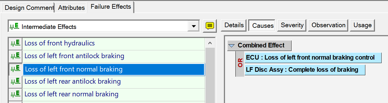
Intermediate Effect Window:
Intermediate effects may also include any combination of object or intermediate effects in their list of immediate (first-order) causes
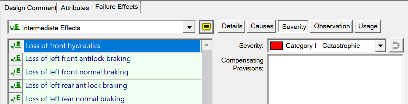
One situation where intermediate effects will be particularly useful is when you wish to create a FMECA chart (with local, next higher and end item effects) for a design that has been modeled in eXpress using only one or two hierarchical levels. In previous versions of the software, local and next-higher effects were based solely on the hierarchical organization of your model (since the difference between object and design effects is their position within the hierarchy). With the introduction of intermediate effects, the hierarchy of effects within an eXpress FMECA study is no longer dictated by the hierarchy of models in your system. For each FMECA study, there are now options on the new Failure Effect Options panel (described later in this document) that allow you to specify which failure effects are to be listed as local and next higher effects in the FMECA. The list of defined failure effects is now color-coded by effect type—when you view object effects, the background of the list is colored a light shade of blue; for intermediate effects, the list is light green; and for design effects, light red (as can be seen in the examples below).
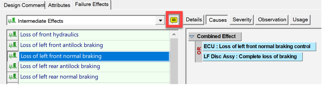
Also, to the right of the list header is a new icon that toggles a mode where the "full effect name" appears in a tooltip when you move the mouse over an entry in the list. This is particularly useful when a model uses long effect names
The Causes tab has been updated to use the same advanced outline control used by the Test Prerequisites and Advanced Test Filtering panels. No more + and – icons. Instead, when you highlight any entry in the outline, a small box appears to the right of that entry. Click on this box and a menu will appear listing the operations that apply to the selected entry. The causes listed in this panel re now alphabetized and color-coded (blue, green or red) to improve readability.
Two icons—one depicting a red arrow, the other a gear—have been added to the Severity tab.
The first icon resets the effect’s assigned severity to the maximum "severity "of its causes. In previous versions of eXpress this could only be done in Grid view or using operations in the main Design menu
The second icon (the one depicting a gear) calls up the Failure Effect Options dialog. This new dialog—as well as the new “Mission Phase” field (disabled in the example above)—is described in the sections on “Mission Phases” and “Intermediate Effects”.
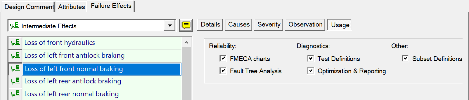
Finally, the Observation tab has been replaced with a new Usage tab that lets you specify whether a
given Failure Effect can be used for test definitions, subsets, FMECA charts, Fault Trees, etc