NOTE: Software on schematics are not shown on computational units and FPGA's. The Analyst needs to add a biidirectional port and bi-directional output flag to these elements to allow software testing within these units. Following is a description of how to setup a software point of test and to utilize eXpress to generate the inputs to these computational elements at the software port and make "path based tests" for these inputs automatically. Using this technique can result in many manhour savings to the analystand will generate most all the software IBIT tests and Software PBIT tests utilized by these elements in the real system("Tests may need to be renamed and fault codes added to agree with System Engineering developed tests.").It will be noted that most outputs from computational systems become inputs to the same or other computational elements and therefore testing the inputs will cover most all internal integrated testing on the system.However, these tests will not test the operational outputs of the system which are not normally part of the internal integrated diagnostics testing. These tests must be generated in a different manner. (Example RF outputs, surface actuators, LED's and physical power test points etc.). Also it will be noted that when model changes are made to update engineering changes to the system; the tests will automatically update their coverage to the new configuration (No test rebuilding to the new system configuration will be required to existing tests).
FPGAs and other programmable components present unique challenges to the Analyst. In this version of eXpress, a pair of batch operations have been added to help eliminate repetitive actions associated with the modeling of test functions on programmable design elements.
Automatic “Create Output Functions” Operation
One of the most tedious parts of modeling programmable components is the definition of “test functions”—functions that represent the component’s built-in testing capabilities.
A new “Create Output Functions” operation allows you to batch-create multiple output functions on a selected port—representing the software test point—based on specified inputs.
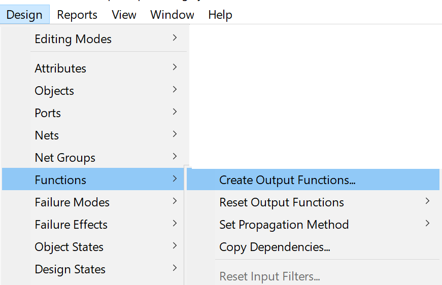
This feature can be invoked by highlighting a single output or bidirectional port and then selecting “Create Output Functions…” from the Functions section of the main Design menu.
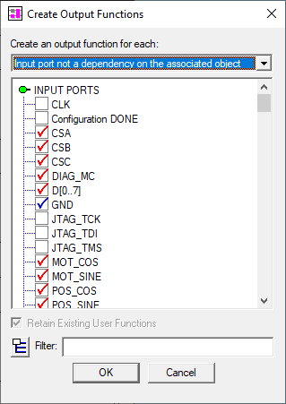
The “Create Output Functions” dialog (depicted at right) will then appear. This dialog will list all input and bidirectional ports on the same object as the highlighted port.
Based on the dropbox at the top of the dialog, ports will be selected by default (using a red checkmark) if they are not currently dependencies of either
any functions defined on the selected output
any functions defined on the associated object
When you click on OK, an output function will be created (on the selected port) for each of the input ports that have a red checkmark.
If you wish for any input ports (such as power and ground) to be dependencies of all of the created functions, then click on the checkboxes for those ports repeatedly until they contain blue checkmarks.
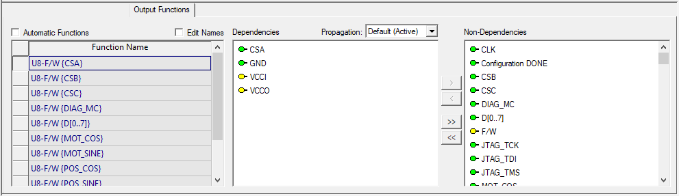
In the example below, output functions were automatically created for a specified batch of input ports (the ones that were marked with red checkmarks on the dialog). For each output function, the name of the input port for which it was created is appended in curly braces.
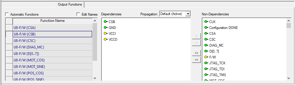
In the example above, the test function for the CSA input is highlighted on the Output Functions panel. In addition to the CSA port, the dependencies also include three other ports—GND, VCCI and VCCO. Because these three ports were marked with blue checkmarks on the “Create Output Functions” dialog, they have been included as dependencies for all functions created in this batch. Here is the second function:
The difference between this function and the first one is that this one depends on CSB, whereas the other depends upon CSA (both ports had been marked with red checkmarks on the “Create Output Functions” dialog).
Using this feature, you can quickly create large sets of output functions that represent the various internal software tests that can be performed when this FPGA is in a testing configuration. Once these output functions have been created, their names can be quickly edited to match the names of the corresponding tests.
The next step is to create a separate test for each function—something that can be easily accomplished with an extension to the mechanism used in eXpress to define probe tests.