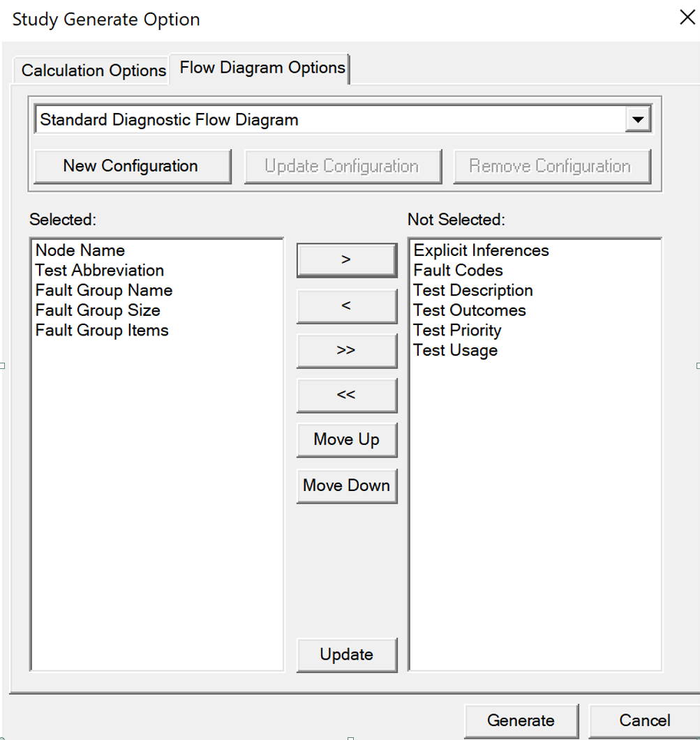
Use the meat grinder ICON to Initiate a diagnostic study after the Diagnostic options have been setup. Then select the Flow Diagram Options Tab. The window shown below will open.This window allows the Analyst to setup Flow diagram templates (New configuration/Update/remove) and/or chose templates already defined which will show in the window as seen below (Standard Diagnostic Flow Diagram).
The twowindows "Selected:/Not Selected:" below allows the operator to configure what items to show in the flow diagram. The items shown in the left window are the default items
Example: Fault codes, when defined, can be included in fault groups cells by moving the “Fault Codes” entry to the desired position in the list on the left. (NB: Fault codes can only be included when the eXpress Maintenance Module is both licensed and enabled).
Also, a new “Update” button has been added to the dialog, allowing the Analyst to rebuild the flow diagram using updated settings without having to rerun the diagnostics.
When a flow diagram is on the screen, selecting one of the option showing in the window above will immediately result in the flow diagram being rebuilt to show the selected option
Flow Diagram Sizing Options: See Setting Diagnostic Study Run-Time Options: