
Products
Custom Views and Automation
Adding and automating custom views and messages allows the diagnostic designer to optimize troubleshooting tasks by directing the technician to the exact task that needs to be performed at each step of the troubleshooting process.
Custom Views
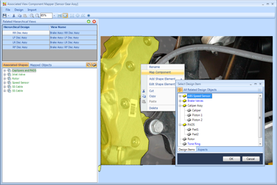
Custom views may be selected from PDF or image files of system drawings, technical manuals or photographs. The component mapper is then used to map the repairable or replaceable items in the design to regions on the view so that when the component is a member of the current suspect set then the component will light up as yellow (partially isolated) or red (fully isolated) to indicate the current troubleshooting status of the component. In addition, all mapped components can be selected to provide details about the objects such as functions, failure modes, tests that can be used to further isolate the object and reference document such as component specification or calibration data. All information available in the design about the components becomes available once the view regions have been mapped to the repairable or replaceable component.

View Messages

View Automation
In addition to selecting which messages will appear on each step in the troubleshooting process, the layout of the screens may also be changed by selecting a specific screen layout to display for each test or fault group in the diagnostic flow. A screen layout is the set of panels and views that are displayed for a test or fault group and may consist of up to 8 different panels with multiple views on tabs in the layout.


